Note: Experimental and work in progress.
Note: Documentation is incomplete and outdated.


The aim is to print functional and strong parts with high flowrate and with reasonable quality at the same time.
Inhalt
Github Mirror, project Homepage
DDPrint FDM firmware: https://github.com/ErwinRieger/ddprint.
Project homepage: http://www.ibrieger.de/close_the_loop_for_e.html.
Video: https://youtu.be/1Kbl9AZd10Y.
Reference printer is a Ultimaker 2 with ddprint installed and some hardware modifications: http://www.ibrieger.de/pimped-ultimaker-2.html
How to do it?
- Add a flowrate sensor to your machine.
- Add firmware support for this flowrate sensor: ddprint
The problem is the grip
Every feeder slips, at least if it has to do some work, that means if there is filament backpressure from the hotend.
The amount of slippage depends on the amount of force the feeder is experiencing. This force/backpressure has several components:
- the force needed to pull the filament from the spool (holder friction)
- the force needed to push the filament to its path to the hotend (bowden, friction)
- the force needed to push the through the nozzle and squish it on the model/buildplate
- and more
Theese components of the needed feeder force depend on numerous factors:
- printing speed
- the hotend and its temperature
- the used filament
- the used nozzle (size, geometry etc)
- and more
The reason for this slippage is the elastic deformation of the filament between successive teeths of the knurled-/hubbed-wheel of the feeder in combination whith the back-force. This elasticity is also the cause that this slippage/grip depends on the amount of force applied to the filament.
Feeder slippage is the ratio of the commanded flowrate and the real flowrate minus 1.0. For example if 10mm³/s filament is requested and 7.5mm3/s, then the slippage is 33%:
slip = (10.0 / 7.5) - 1.0 = 0.33
The other way around, grip is the reciprocal of slip, so in the previous example we have:
grip = (7.5 / 10.0) = 0.75
That is 75% grip.
Feeder slippage means underextrusion, some amount of material is missing from the print. So when there is always feeder slippage and there is always underextrusion to a certain degree.
The worst case of this slippage is feeder grinding where the filament is milled of by the feeder wheel and the filament transport almost stops. In this case slippage is near 100% and grip is nearly 0% respectively, this is maximum underextrusion and a failed print is the outcome of this situation.
But how does it work nevertheless
Several factors make this underextrusion less notable:
- firmware hacks, like a optimistic e-steps value, measured um2-2 e-steps are 275, orig um2 esteps is 282, 282/275=1.025 -> 2.5% overextrusion
- people don't see/know it (walls still closed even with 50% slip/underextrusion, todo: prove this), or they do not realize that it's underextrusion what they see.
- people fiddle with their printers and the various settings (extrusion multiplier, flow etc) until they get a (randomly) satisfactory result
- most of the time the advice is just: print slower.
In summary:
- there is a extrusion limit that depends on the printer and various other parameters (mainly filament, nozzle diameter and hotend temperature).
- most of the time you dont't know where this limit is
- you have to operate your printer (way) below this unknown limit to avoid underextrusion and get good prints
Here comes the flowrate sensor into play: We can measure the melting capability of our printer (for a given filament/nozzle combination) and therefore we can operate our printer near its maximum performance.
The flowrate sensor FRS
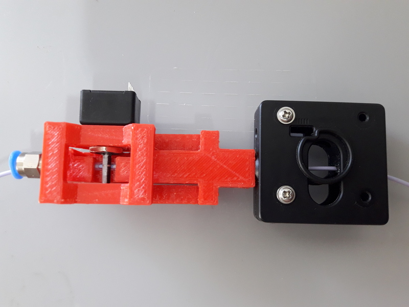
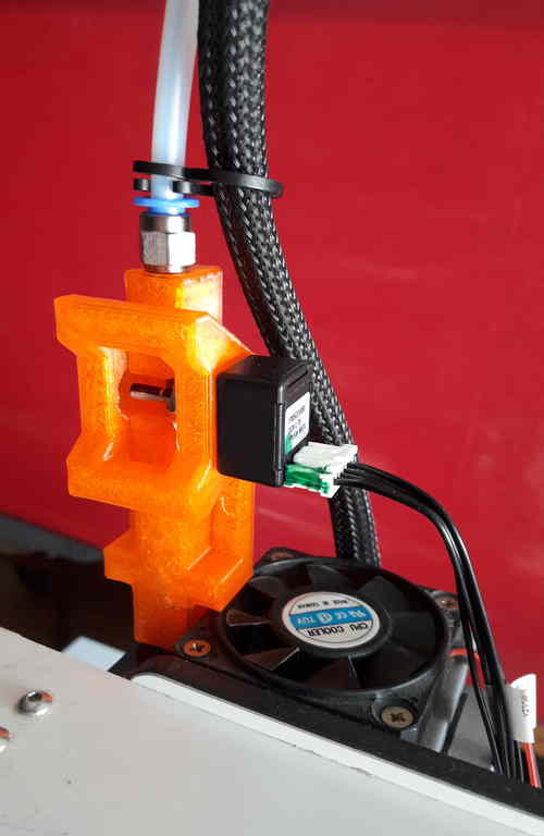
The flowrate sensor is used to measure the speed of the filament after it exits the feeder. Using the diameter of the filament, we can calculate the flowrate from the filament speed and use this information to control the speed of the printer, amongst other things.


The current form will only work with bowden type printers. Todo: describe mount of flowrate sensor in front of feeder or the optical sensor looking at idler wheel version of the FRS and its drawback.
Note that this is not just a filament presence/runout sensor or similar filament sensor.
The sensor consists of the following parts:
- A Bourns EMS22AFS incremental sensor. It is connected to the SPI bus of the printer mainboard.
- A 3d printed body: feedsensor.stl, note: this model contains some custom supports.
- Some additional parts like a teflon tube and a pneumatic connector to connect the bowden tube of the printer.
Video with sensor in action: https://youtu.be/ESc9FN7LjSw.
Other usages, advantages of the flowrate sensor
| Todo: | ... |
|---|
- Helps to avoid underextrusion or filament grinding in many cases: hotend to cold, first layer problems and so on.
- Allows to record the tempearature/flowrate profile a filament by extruding some filament at varying speeds. This data is the base for the AutoTemp algorithm.
- Auto-calibrate the feeder.
- Display the health (=grip) of your extruder system while printing.
Easier slicing, simple gcode
| Note: | Simplify3d is used as of this writing. |
|---|
ddprint eases the generation of gcode with your slicer because many of the advanced features of the slicers (i call it slicer hacks) can be ommited, for example:
- Use the same speed everywhere, firsts layer-, outline-, infill-, support-speed are all the same base printing speed.
- Forget about temperature settings in the slicer, ddprint is doing the temperature control (todo: section about autotemp) itself. Gcode commands about temperature are ignored by ddprint.
- Disable stuff like coasting or wiping.
- Don't use dynamic acceleration/jerk control or such things, just bare gcode.
The (automatically measured) material profile gives a picture of the hotend melting capacity (= max. flowrate) for a given machine/filament combination. This eases the determination of a good printing speed.
Simplify3d example slicer settings in https://github.com/ErwinRieger/ddprint/tree/master/examples/s3d_profiles.
Other slicer settings for ddprint
Some more settings that diverge from the default (S3D) profile:
- Infill Outline Overlap: default of 15% is increased to 35%. With linear advance there is no blob at the end of a segment, so this value is increased (Todo: check if this is to high).
- Retraction between layers: default is on but switched off, linear advance releases the presssure in the hotend at the end of a layer, so the reatreaction is not necessary here (Todo: compare quality of two objects with and without this setting).
Result
Print reliable with high flowrates while still getting good quality.
Video: https://youtu.be/1Kbl9AZd10Y.
Thanks
Thanks to all open/free software people that make this all possible.
Links
- https://www.bourns.com/docs/Product-Datasheets/EMS22A.pdf
- http://github.com/benhoyt/protothreads-cpp
- http://bernhardkubicek.soup.io/post/168776124/Another-acceleration-extrusion-compensation-for-repraps
- http://github.com/Ultimaker/Ultimaker2Marlin, http://github.com/MarlinFirmware/Marlin
- http://github.com/makerbot/s3g
- http://github.com/Traumflug/Teacup_Firmware
- http://github.com/ambrop72/aprinter
- http://www.repetier.com/documentation/repetier-firmware/
- http://github.com/triffid/SoupCup_Firmware
- http://github.com/JustAnother1/Pacemaker
- http://github.com/KevinOConnor/klipper
- http://github.com/mtu-most/franklin
- http://elm-chan.org/docs/mmc/mmc_e.html
- http://www.hwml.com/leibramp.pdf
- http://www.embedded.com/design/mcus-processors-and-socs/4006438/Generate-stepper-motor-speed-profiles-in-real-time
- http://www.extrudable.me/2013/04/18/exploring-extrusion-variability-and-limits/
- https://github.com/mrjohnk/PMW3360DM-T2QU