Some (quick & dirty) notes taken while installing/porting ddPrint on a Ender5 (pro).
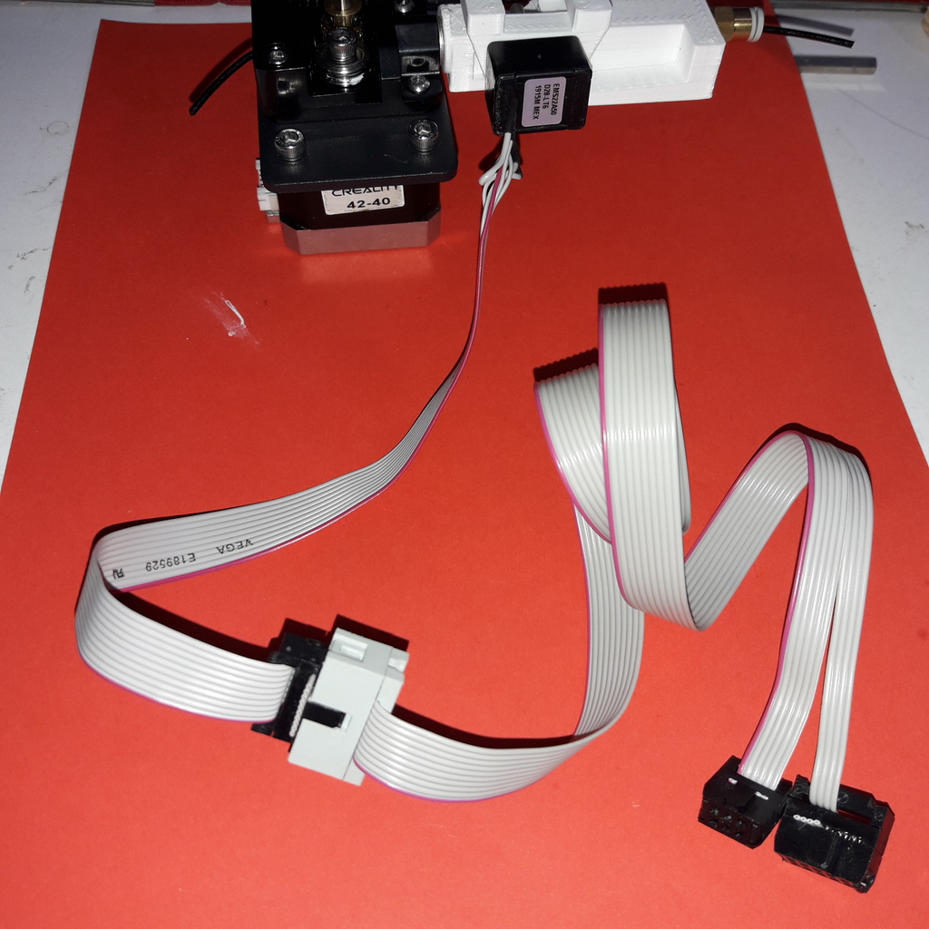
Mount Flowrate sensor
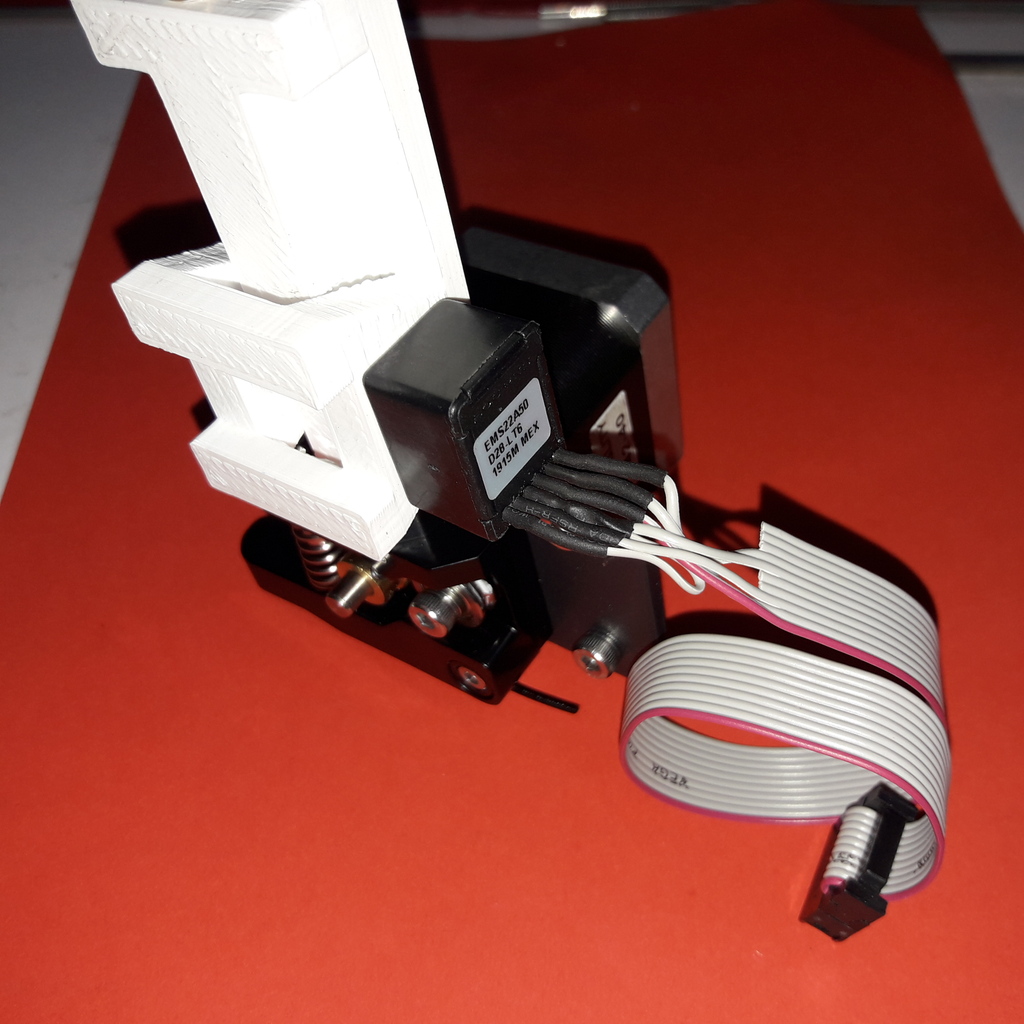
Print sensor housing and mount incremental sensor.
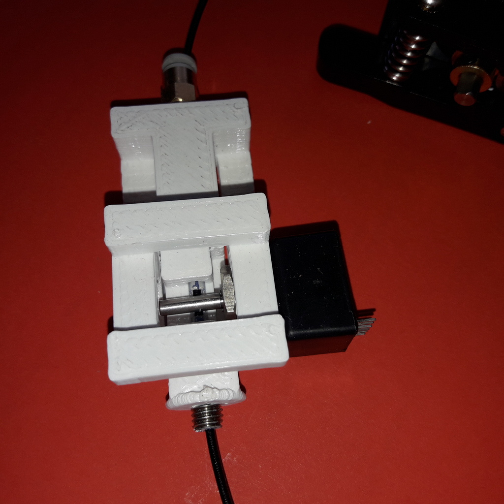
Todo: Upload and link Sensor housing stl.
Mainboard
Creality3d V1.1.4 CPU: Atmega 1284p Clock: 16 Mhz
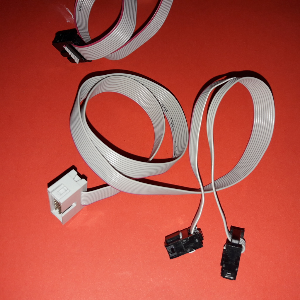
Flowrate sensor connection
Board schematic: https://raw.githubusercontent.com/RudolphRiedel/CR-10_wiring/master/Ender3_schematic.PDF
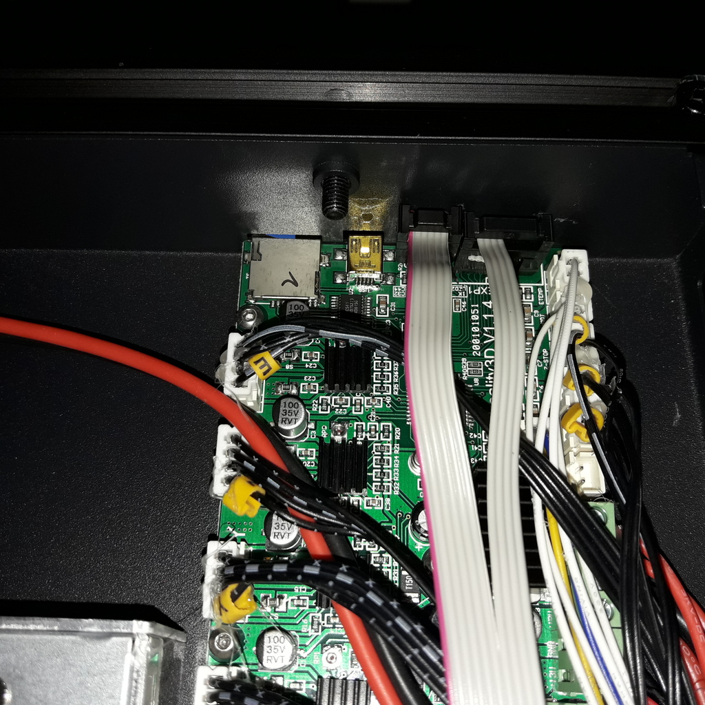
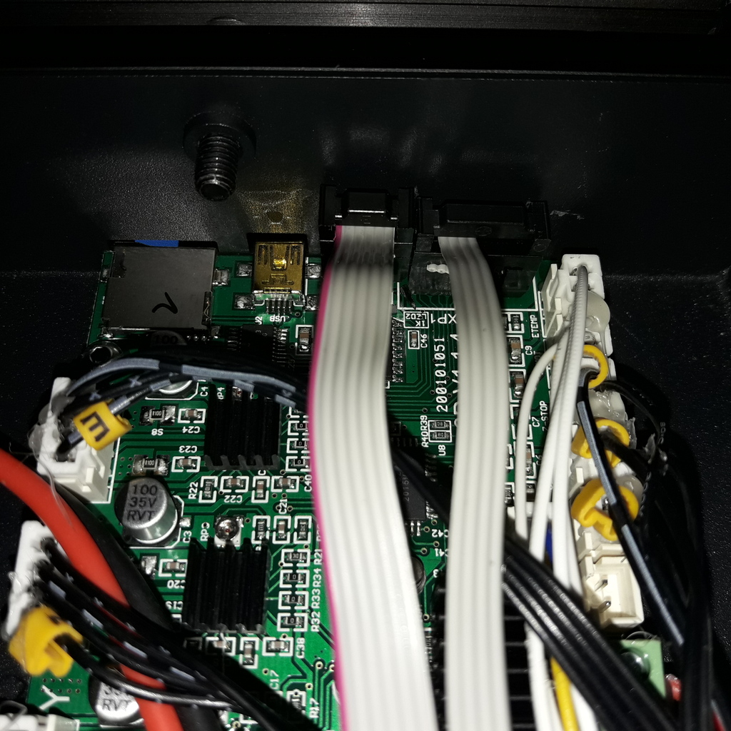
FRS is connected tho the SPI bus using 6-pin ISP header and one pin of the EXP1 header:
Connector ISP:

1: MISO        --> FRS MISO
2: +5V VCC     --> FRS +5V
3: SCLK        --> FRS SCLK
4: MOSI
5: Reset
6: GND         --> FRS GND

Connector EXP1:

1: Beeper      --> FRS ChipSelect
| Note: |
|---|
Achtung EXP1 ist falsch herum bestückt/bezeichnet (ist um 180 grad gedreht, die nase ist also auf der falschen seite, pin1 <-> pin10).
Damit ist EXP1/pin1 (also unser FRS CS signal) der beeper anschluss welcher mit CPU-pin 33 ADC4/PCINT4/PA4 verbunden ist. --> OK, nachgemessen.
Had to remove the connector housing of the EXP1 header to make room for the ISP connector:
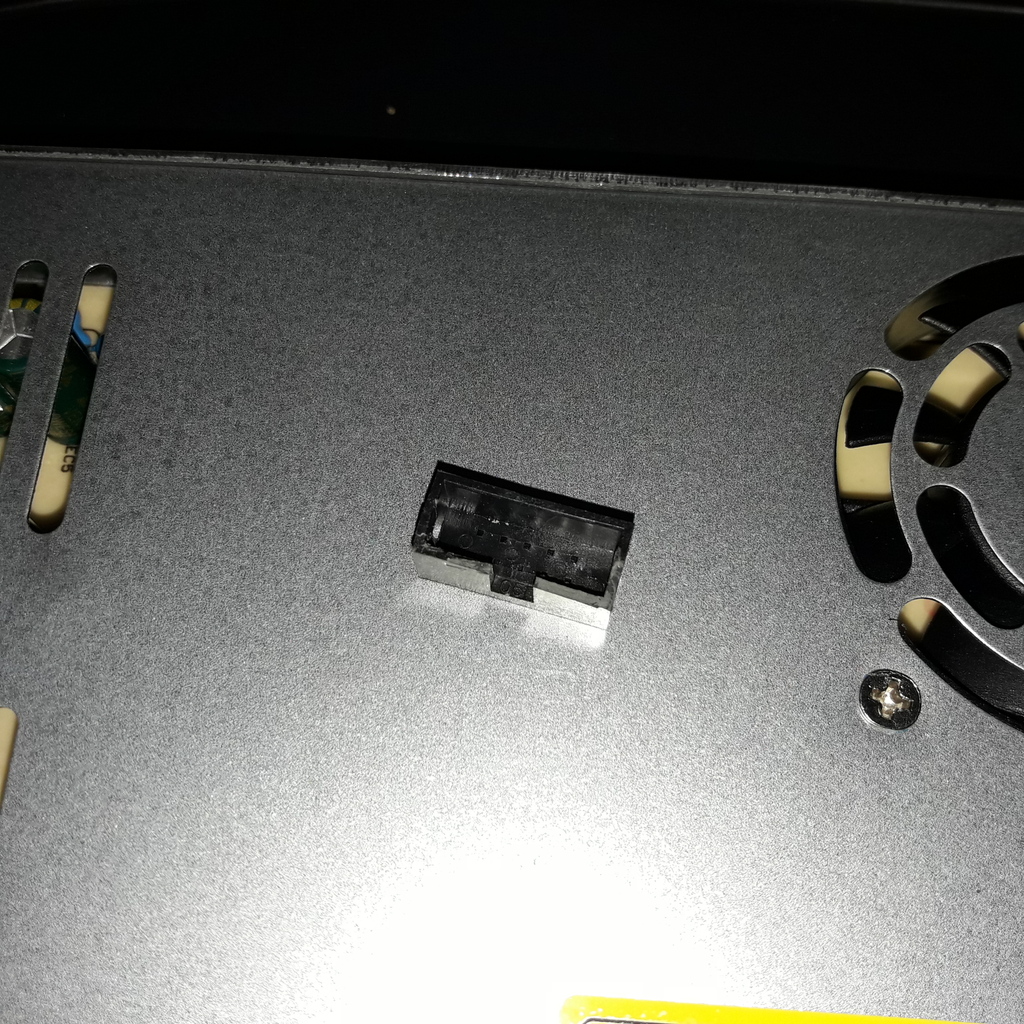
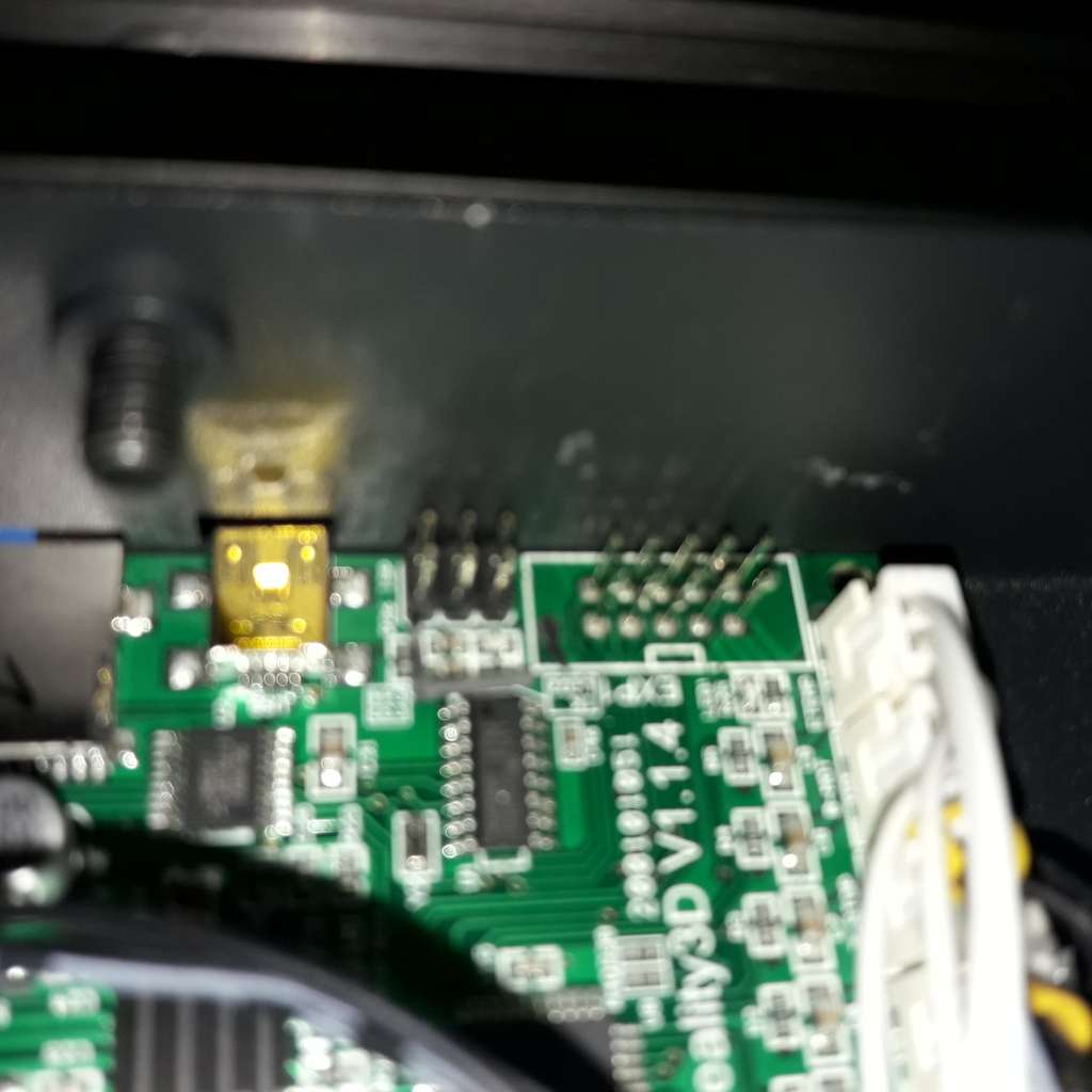
FRS connected to mainboard headers ISP and EXP1:
Miso pullup problem
https://github.com/greiman/SdFat/issues/122
Ender5 sdcard funktioniert anscheinend problemlos am UM2.
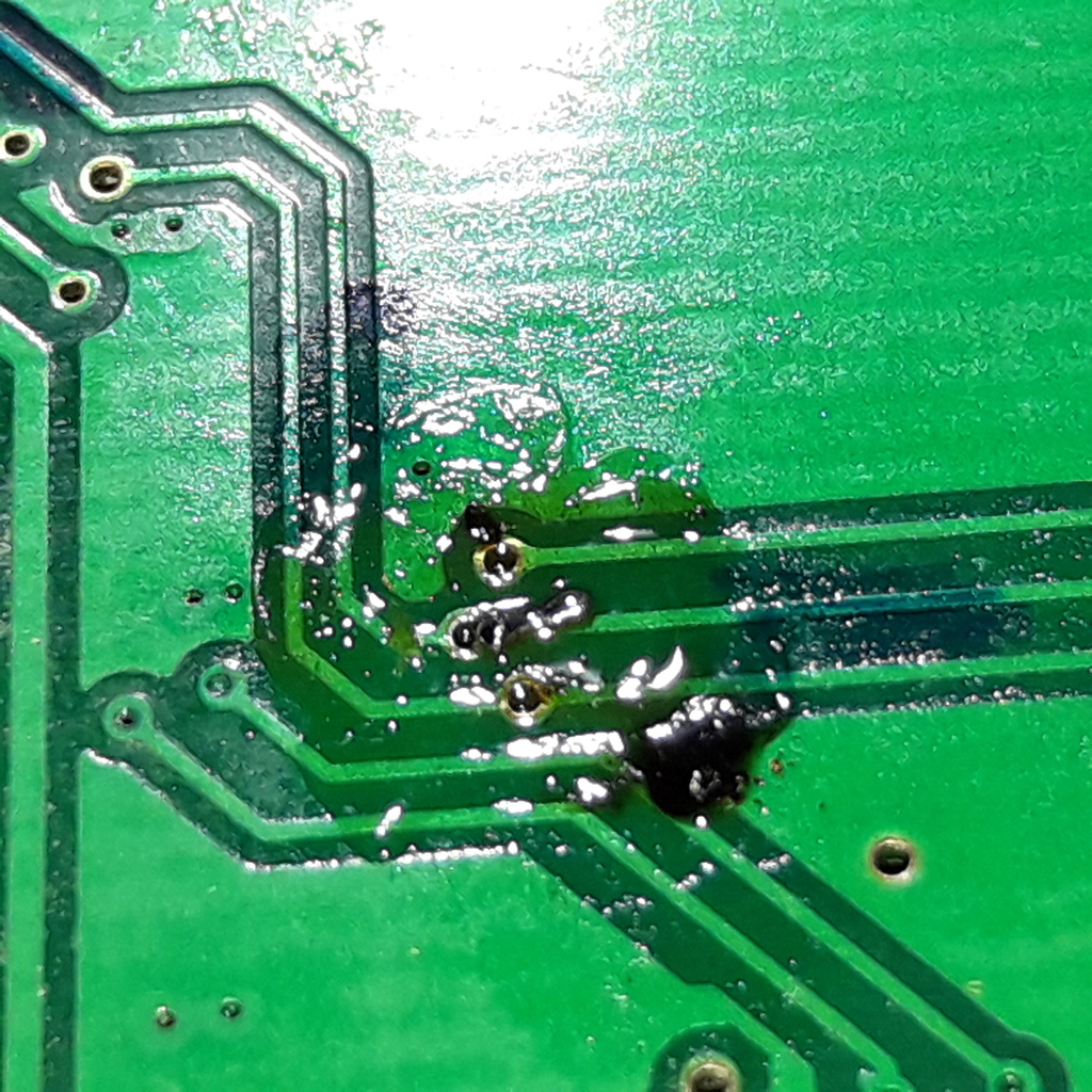
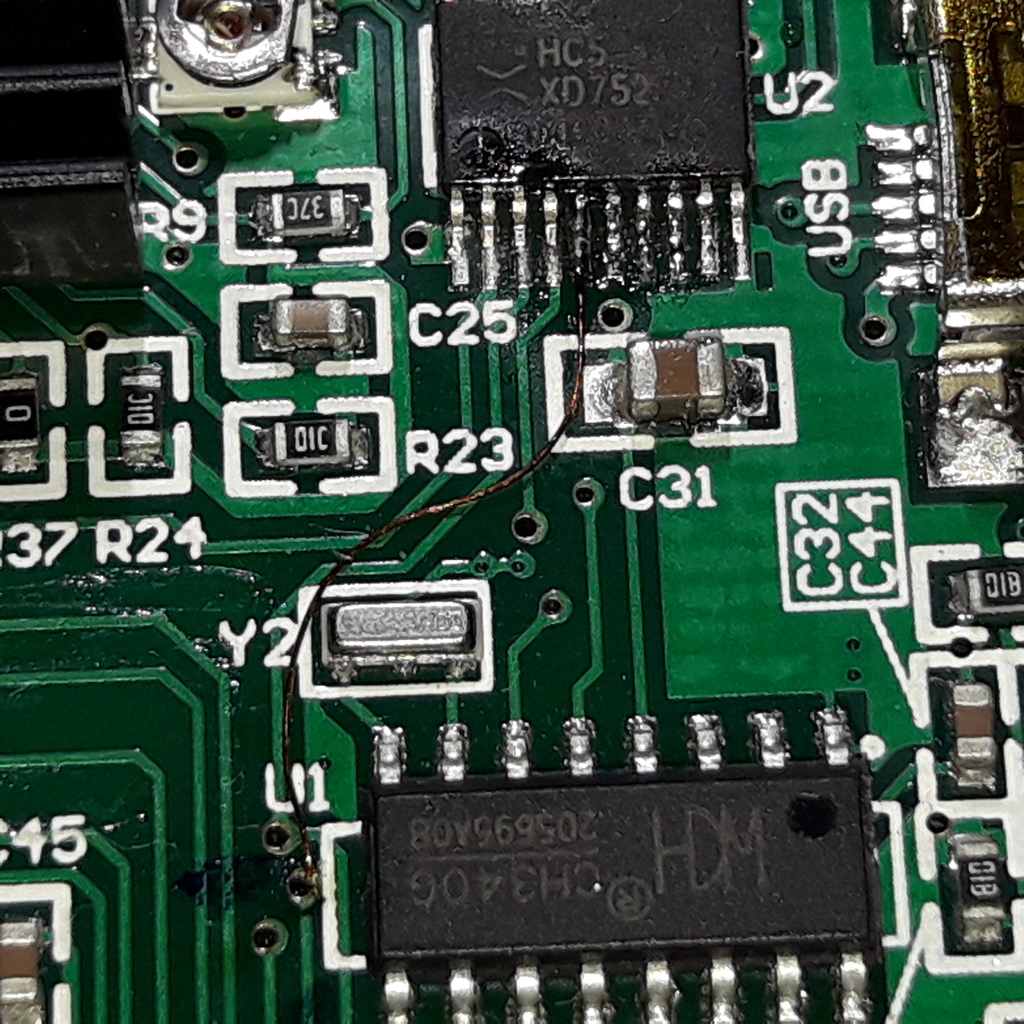
Level converter/driver mod
- Questionable: floating unused inputs?
- Questionable: miso goes through level converter but output enable pins (OE1/OE2) are always enabled -> bus conflict if other devices on SPI bus (including ISP programmer)?
- No pullup on sd card chip select (SS)?
Did a hardware modification on the mainboard to allow other devices on the CPU SPI bus. This includes the disconnection of the MISO line after the buffer and connecting it directly to the SPI bus.
Case cooling fan
Case/electronics cooling fan "fan" is connected in parallel to the parts cooling fan ("fan1")!?
Mods
Hotend
"MK8", 40w?
Luke's hotend mod
Applied Luke Hatfield's hotend mod (https://www.thingiverse.com/thing:3203831), but using a o-ring 4.5 x 2mm instead of a washer. The o-ring shall center the ptfe inliner and press down it against the nozzle.
Bed
Cable strain relief https://www.thingiverse.com/thing:3443100.
Electronic relocation
Relocated electronics case to the back of the printer for better cable management.
Brackets to mount electronic case: https://www.thingiverse.com/thing:3830464/files. Corner brackets from here: https://www.thingiverse.com/thing:3939592.
Z-Axis fix
Z-Screw gets stuck when bed is lowered, Z-Screw and Z-Rods are not aligned. Added thin washers/shims between frame and the Z-Rod brackets.
Together with the electronic case relocation this gives us more than 320 mm of Z-height.
Thermistor types
Heated bed and hotend both have a EPCOS 100k termistor in series with a 4.7k pullup resistor, Thermistor type choosen is B57560G104F.
R25 = 100k
R150 = 1.6419k
R250 = 0.2261k
Generate thermistor table with:
python scripts/thermistor_table.py > /tmp/tt.c
Firmware
Install atmega1284p arduino core from https://github.com/Lauszus/Sanguino.
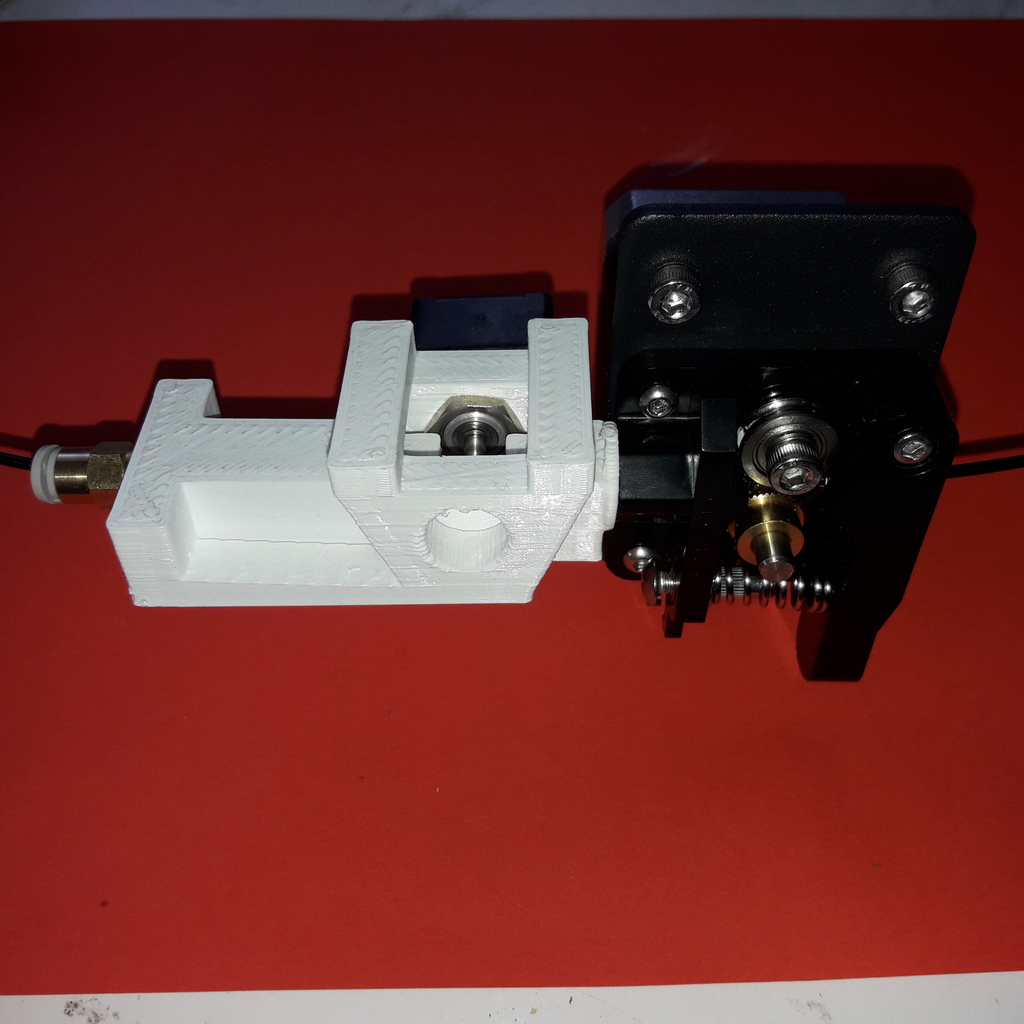
Feeder
Feeder is MK8 style, feeder wheel diameter is 10.95mm, assumed circumfence:
(10.95-0.1) * pi = 34.1mm
Feeder spring set to it's lowest/weakest setting and removed the threaded rivet to lower the spring force even more.
Stepper current
VREF = 8 * Imot * 0.1ohm
Increased stepper motor vref/current to:
X: 0.65V -> 0.81A Y,E: 0.75V -> 0.94A Z: 0.60V -> 0.75A
Bill of materials
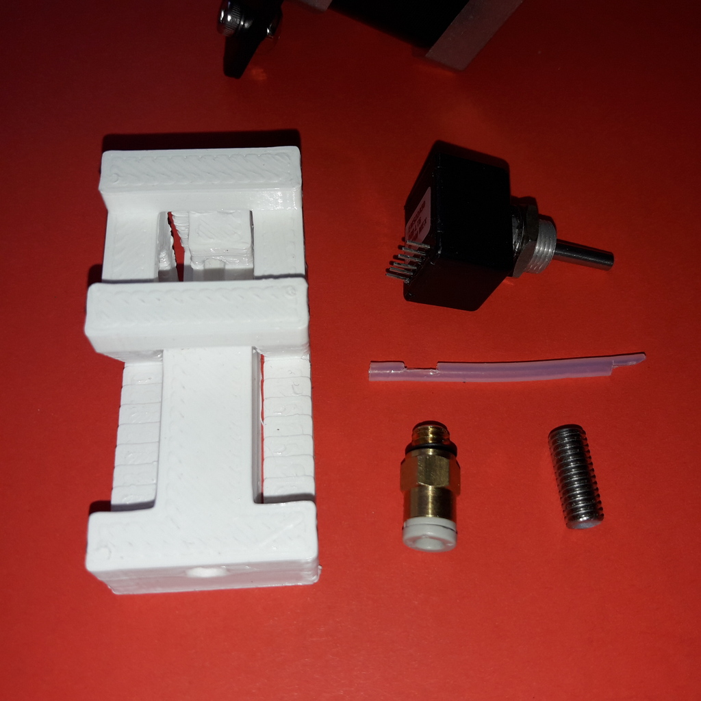
FRS:
- EMS Sensor
- FRS housing
- 6mm stahl heatbreak mit teflon inliner (aus 30mm heatbreak können 2*15mm gemacht werden).
- 4mm pneumatic coupler (M6)
- 3/2mm ptfe liner
- Ribbon cable and connectors
Hotend:
- 0.8-er nozzle
- O-ring 4.5 x 2 mm
Misc
For better support of the wobbly printbed i printed and installed the Ender 5 bed support_flat by freudi85 (http://www.thingiverse.com/thing:3447280).
Notes
Mainboard power supply per USB, that means it is always running if USB is connected, even if main power supply is switched off. Printer state gets out of sync if power is switched off, no reset of printer without disconnecting USB and powering off.
Todo: improvements
- Bowden tube pops out of hotend after some time. Bowden tube moves inside pneumatic coupler and develops a grove. Check how we can improve this (perhaps some clamping of the ptfe tube).
- Z-Endstop seems to be not very reliable/repeatable.
Nice to have
- Ventilator feeder da direktantrieb (spannung bereits am frs-kabel vorhanden).
- Stronger heater (50W)
First prints
Some prints done with the Ender5 ddPrinter (more here):
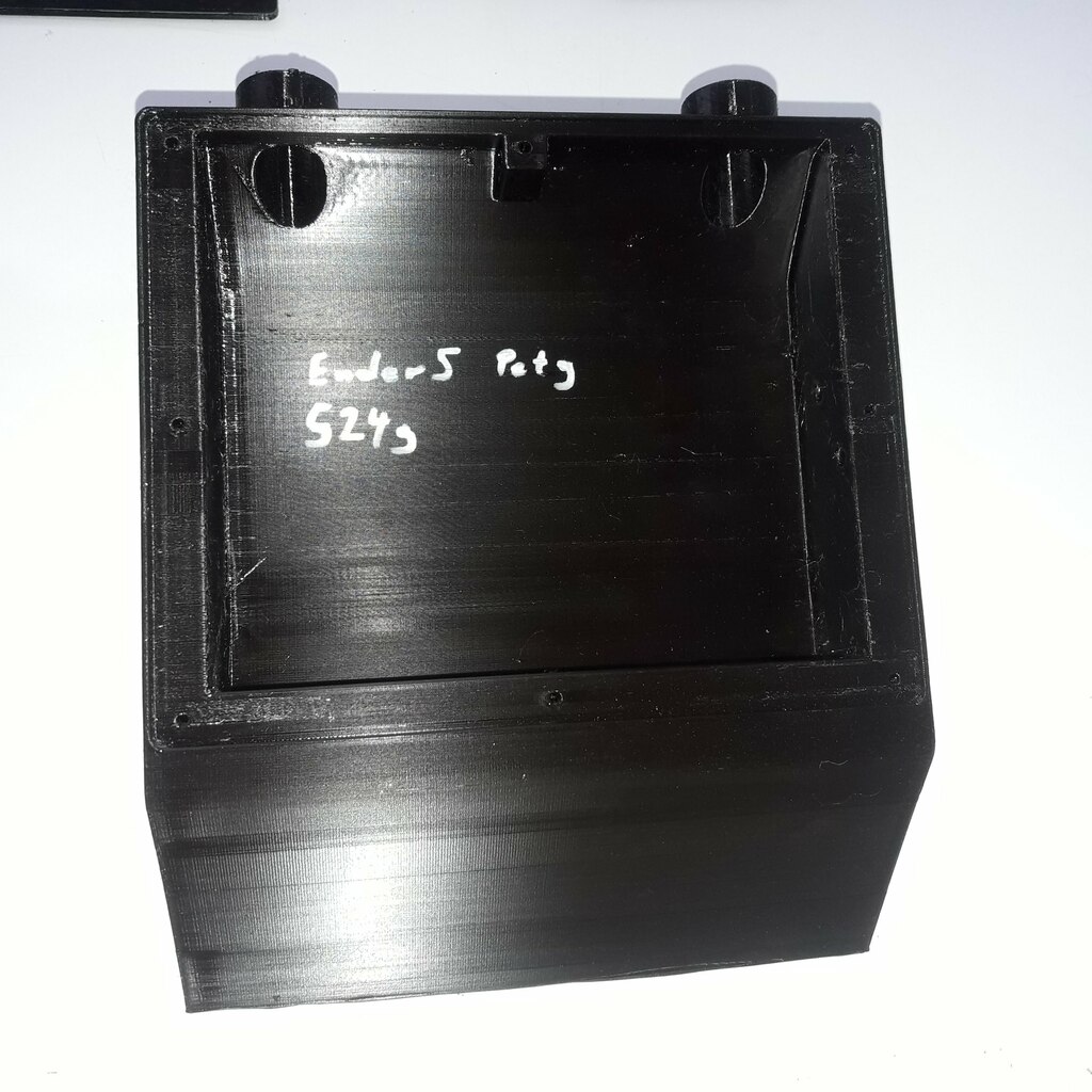
XCat remote control housing, printed with Herz Petg filament, sliced with 0.8 mm nozzle, 0.25 mm layerheight and 65 mm/s printing speed (this is a max flowrate of 13 mm³/s). Weight of the printed part is 524 g, this is 95 % of the slicer-estimated weight (550 g, density 1.29 g/cm³).
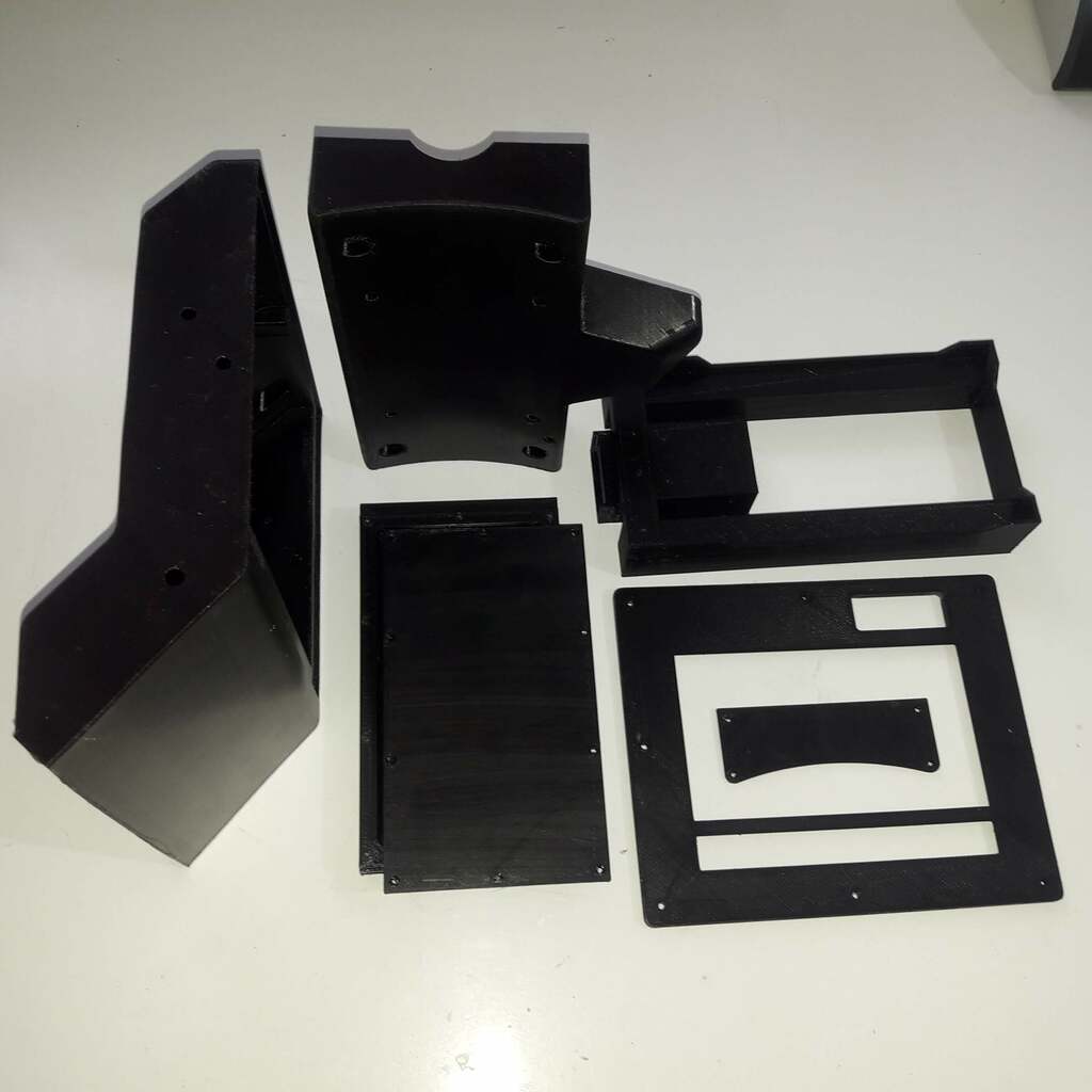
More XCat parts.